




Installing automated glass processing equipment demands meticulous groundwork that extends far beyond simply clearing floor space. Proper foundation preparation directly impacts equipment longevity, operational precision, and worker safety. A glass loading table—whether it's the primary loading station where cutting machines receive glass, the patching station positioned behind for preparation tasks, or the alternating workstation designated for unloading—requires structural support engineered to withstand continuous heavy loads and vibration. Understanding these foundational principles prevents costly retrofits and ensures your facility operates at peak efficiency from day one.
Understanding Heavy-Duty Glass Loading Tables and Foundation Requirements
What Defines Heavy-Duty Glass Loading Equipment
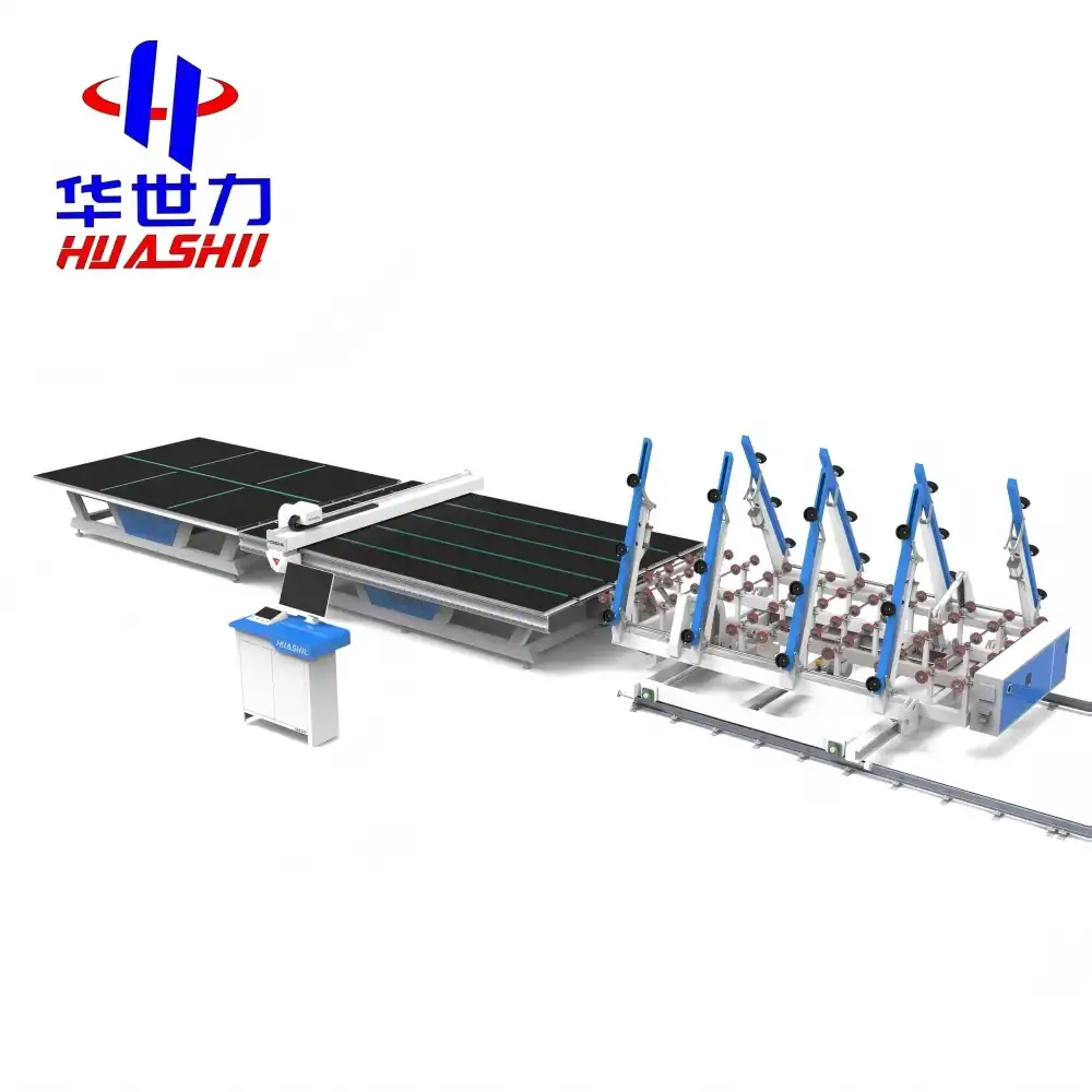
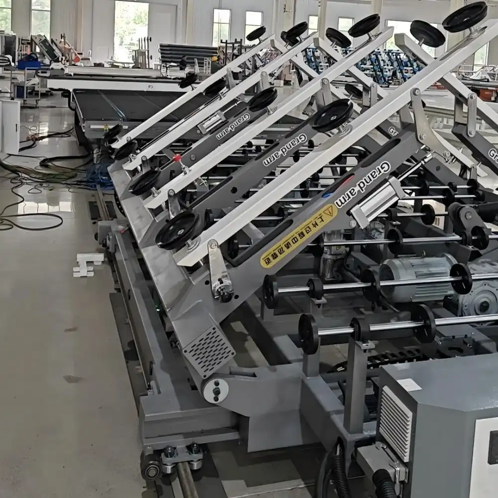
Glass processing units are the most important part of modern lines that make ornamental glass, curtain walls, and furniture. These special surfaces hold up huge sheets—sometimes more than 3,000 kilograms—and allow for exact placement with the help of motorized rollers or air flotation systems. The filling station is where the raw glass meets the cutting tools, so it needs to be perfectly level to keep the sheet from deforming. Behind this, the repair station provides a controlled space for cleaning up the edges and checking the quality of the work before the material moves on to the next step in the production process. Finished items are handled by alternating workstations, so the material flow cycle is completed without any delays.
Different base needs are created by each type of station. Loading areas are subject to repetitive dynamic loads because automation systems move and lift glass many times during shifts. Patching zones need platforms that are stable and won't move, so they stay in line with the equipment next to them. When processed glass falls onto unloading desks, they have to take the pressure. Ignoring these details can cause equipment to become out of line, wear faster, and result in output being rejected.
Critical Foundation Specifications for Industrial Glass Equipment
Load-bearing capability is engineers' first concern. A standard air float glass loading table installation requires supports that can handle 150 to 200% of the maximum capacity, plus or minus safety margins and dynamic load factors. The concrete slabs may withstand 5,000 to 15,000 kilos per square metre, depending on equipment setup.
Weight distribution varies greatly by station type. The pneumatic lift points and roller assemblies of loading platforms bear the highest weight, causing stress. In these crucial areas, foundation designs must contain strengthening zones. This normally requires extra rebar or steel plates. Patching stations distribute weight more evenly, but precision measurement equipment requires greater smoothness tolerances—often within 2 millimetres across the surface—to keep straight.
Stable ground is key to long-term success. Facilities constructed on loose clay soils or with high water tables may settle, shifting equipment alignment. Geotechnical investigations identify these risks during planning. Engineers may pick the best solutions to stabilise the soil or create deep foundations to shift weight to stronger layers below the troublesome levels.
Vibration control protects equipment and product quality. In glass manufacturing, cutting, moving materials, and air generator cycles generate mechanical oscillations. Isolation pads or spring-mounted supports prevent these vibrations from reaching surrounding workstations. This reduces processing-related glass micro-fractures and machine part stress.
Step-by-Step Foundation Preparation Process
Conducting Comprehensive Site Assessment and Soil Analysis
The foundation design standard is set by a professional geotechnical study. Engineers take soil samples at regular intervals that match the size of the equipment footprint, which is usually every 3 to 5 meters across the installation area. The bearing capacity, compaction traits, and moisture sensitivity are all found through laboratory research. These are all factors that directly affect the choice of foundation type. If you dig a hole and find weak soil below 100 kPa, you need to replace the soil, dig deep foundations that go all the way to the load-bearing layers, or use techniques like dynamic compaction or soil-cement columns to improve the ground.
The depth of the water table affects how things are built and how long they last. For building projects with shallow groundwater, dewatering systems and sealing measures are needed to stop capillary wetness from moving into concrete structures. Testing procedures should look at how groundwater levels change with the seasons and make sure that plans are based on the worst-case scenarios, not just what was seen during short site visits.
Engineering Foundation Design with Precision Load Calculations
A thorough load analysis for a glass loading table turns the specifications of the tools into the building's needs. Engineers figure out the weight of the tools, the capacity of the glass material, the live loads, and the impact factors based on the rounds of automatic handling. These forces work together to set the minimum thickness of the concrete and the schedule for adding reinforcements. Reinforced concrete slabs 300 to 400 millimeters thick are used in most setups. However, 500 to 600 millimeters deep may be needed for heavy-duty designs that support multiple integrated workspaces.
Patterns for reinforcement must take into account both bending loads and crack control. Standard practice uses two-layer rebar mats spaced 150 to 200 millimeters apart, placed so that they cover enough concrete and allow the structure to go as deep as possible. Extra support is added to high-stress areas under where the equipment is mounted. This is usually done with steel plates that are welded to anchor studs that stick out and hold the machinery directly to the foundation.
Implementing Installation Best Practices for Ground Preparation
In industry, the correct concrete requirements provide durability. Mix designs should provide 30 MPa compressive strength after 28 days of curing. Lower water-to-cement ratios improve density and chemical protection. Silica dust or fly ash enhances long-term strength and reduces permeability, preventing steel from rusting in moist areas.
Excavation sets the foundation height and makes place for sub-base materials. Contractors remove topsoil and organic debris from stable soils. Grading the trench floor helps water drain from the foundation borders. Keeping the laser level correct throughout this stage prevents costly concrete placement modifications.
Sub-base construction provides a sturdy, flat surface for concrete. Carefully graded gravel or crushed stone placed in 150-millimeter lifts supports and aids drainage. Geotextile cloths between local soil and aggregate prevent mixing, reducing foundation strength. Nuclear density gauges or plate load compression tests verify the 95% standard Proctor density before proceeding.
The foundation's shape and height depend on form placement. Steel channels or dimensional wooden forms streamline concrete installation. Form heights are checked regularly to ensure they match the equipment manufacturer's installation plans. Anchor bolt templates within forms align fixing holes with equipment base plates. This prevents field cutting, which weakens structures.
Executing Quality Verification and Compliance Inspections
New concrete installation requires collaboration to prevent cold joints and segregation. Filling and shaking the material around the reinforcements eliminates gaps and maintains structural continuity. Laser screed technology or precise hand-floating techniques are utilised for surface finishing to achieve flatness requirements, depending on task size. Curing chemicals or wet burlap maintain air moisture as strength grows.
Tests on hardened concrete validate design assumptions. To ensure tolerance, optical levels are used to verify the compressive strength and smoothness of core samples after hardening. Corrective steps are performed for large modifications. Fine grinding may repair tiny elevation discrepancies, while removing and rebuilding the complete piece can solve strength issues.
Anchor bolt verification checks equipment placement before delivery. Technicians ensure bolt spacing, projection heights, and verticality meet manufacturer specifications, typically within ±3 millimetres horizontally and ±5 millimetres vertically. Filling gaps beneath equipment base plates using non-shrink cementitious materials ensures that all surfaces contact and that the load is uniformly distributed after installation.
Best Practices and Case Studies in Foundation Preparation
Advanced Techniques for Moisture Control and Waterproofing
Infiltration of moisture harms foundations in numerous ways. Capillary action draws groundwater through concrete fractures, dampening it, speeding steel corrosion, and damaging machine mounts. Vapour barriers built of 200-micrometer polyethylene sheets beneath slabs prevent this moisture pathway, but connections must be lapped and sealed.
Excavations for below-grade foundations should have external waterproofing membranes on their walls. Rubberised asphalt or bentonite clay panels block water. Water that enters these waterproofing systems is directed to perimeter drains by drainage composites before hydrostatic pressure ruins the membrane.
In climate-controlled buildings, interior moisture management reduces condensation. Warm, humid air condenses on chilly concrete. This damages floor coverings and increases slip risk. Flexible sealers or insulating coatings decrease concrete's surface temperature, reducing condensation and maintaining its strength.
Vibration Dampening Solutions for Sensitive Glass Processing
Isolation technology keeps equipment safe from outside sources of sound while keeping oscillations made by tools used to make glass in check. Putting neoprene pads between the foundation and the bases of the equipment can absorb high-frequency vibrations, but as the equipment gets heavier, they don't work as well. Spring isolators work better for heavy-loading stations because they let you change the resonant frequencies that dampen certain vibration bands that match the speeds of the equipment.
In strategies for controlling vibrations on a glass loading table, inertia blocks do two things. These huge concrete structures, which often weigh several times the weight of the equipment they support, stop operating forces from moving the equipment while dropping the system's natural frequency below the ranges of excitation. When you mount equipment on inertia blocks that are separate from the floor slabs around them, you create mechanically decoupled systems that stop vibrations from reaching workstations next to them.
Real-World Implementation: Automotive Glass Facility Expansion
A company in the Midwest that makes car glass had trouble with the foundations when they tried to add automatic loading stations to a building that was built on expansive clay soils. The first tests showed that the seasonal soil moved more than 25 millimeters, which is much bigger than what is acceptable for equipment used for cutting glass precisely. Helical pier foundations that went 8 meters deep into stable bearing layers were used as an engineering solution. This eliminated the risk of settlement and saved the cost of fixing the whole building.
New foundation pads were cast separately from the rest of the building and supported by helical piers that were inserted through existing floor slabs. This method kept new equipment from being affected by building moves and kept production as steady as possible while the building was being built. Monitoring after installation showed that the base stayed stable within 1 millimeter for two years, through multiple wet-dry cycles. This proved the design method and allowed precise equipment calibration, which increased cutting yield by 3.2%.
Distribution Center Success: Prefabricated Foundation Systems
To meet agreed-upon shipping dates, a glass distribution center needed loading and patching sites to be set up quickly. Using traditional cast-in-place foundations would have taken six weeks, which was too long for the schedule. The project team asked for precisely sized prefabricated concrete foundation blocks to be made off-site. These blocks were then installed and leveled using hydraulic positioning systems over the course of two days.
Anchor studs were built into prefabricated blocks, so there was no need to drill holes in the field, and fewer mistakes were made during installation. By grouting the joints between the blocks and the prepared sub-base, one-piece structures were made that were the same as cast-in-place structures. This method cut down on construction times by 70% while improving accuracy in measurements, allowing equipment to be put into service as soon as it arrived. The first year's production statistics showed that there was no unexpected downtime due to foundation problems. This is different from the industry average of about 2% to 3% for quick installations.
Maintenance and Long-Term Performance Optimization
Establishing Effective Foundation Inspection Protocols
Visual checkups every three months detect new issues before they harm equipment. Technicians check foundations for cracks, flaking at anchor points, and water infiltration. Take photos of crack patterns and use measured comparators to quantify their spread to monitor how rapidly things are breaking down and determine whether to act. Engineers must inspect and fix cracks larger than 0.5 millimetres.
Annual precision surveys assess the foundation's elevation safety using optical levels or laser scanning. Readings may be compared to standard data from the first installation to determine patterns of settlement or heave induced by underground conditions. If elevation fluctuates more than 3 millimetres, investigate the reasons. These may include groundwater levels, soil consolidation, or inadequate sub-base compaction. Fixing these faults prevents them from worsening and necessitating equipment replacement.
Anchor bolt integrity impacts performance and safety. For vibration-free usage, twice-yearly torque inspections ensure the mounting gear maintains its preload. Lower torque bolts are retightened per the manufacturer's specifications. However, persistent loosening indicates foundation movement, which requires structural correction rather than hardware maintenance.
Implementing Predictive Maintenance Through Sensor Technology
Current condition monitoring systems make foundation care proactive rather than reactive. Embedded vibration monitors regularly assess the base's response characteristics for variations in resonance frequencies that indicate construction problems like fractures or support failure. With fast, wireless data delivery, machine learning algorithms may detect subtle pattern changes weeks or months before harm is visible.
When the floor settles or rises, equipment bases with tilt sensors monitor angle changes. At 0.01 degrees, inclination variations are invisible but large enough to affect equipment calibration. Comparing this data across annual cycles helps us distinguish between normal thermal expansion and progressive settling that requires fixing.
Moisture sensors at the foundation depth monitor groundwater levels and water entry into protective systems. When moisture levels are high, investigations are initiated before water reaches the concrete reinforcement, preventing corrosion. When you integrate moisture data with weather patterns and a building's drainage system, you can see how effectively water is handled and make preventive modifications.
Conclusion
Foundation preparation for a glass loading table creates the solid base that makes glass processing operations run smoothly. From the initial soil study to long-term performance tracking, each step requires careful attention to detail that pays off by making sure the equipment works well and lasts longer. The difference between good and great foundations is often not in the way they look, but in how many years they work without any problems versus how often they have alignment problems and parts fail before they should. Engineering foundations that fit the needs of specific equipment, like loading stations, patching areas, or rotating workspaces, mean matching short-term cost concerns with long-term costs. By engaging in good foundation design, quality building, and organized upkeep plans, businesses can gain a competitive edge by ensuring consistent output quality and reducing downtime.
Frequently Asked Questions About Glass Loading Table Foundations
1. How thick should concrete foundations be for automated loading equipment?
The thickness of the foundation depends on the weight of the equipment, how it works, and how much weight the soil can hold. Standard installations need reinforced concrete slabs that are 300 to 400 millimeters thick. Heavy-duty configurations that support integrated production lines may need slabs that are 500 to 600 millimeters thick. These needs are greatly affected by the structural conditions of the site. For example, weak soils need bigger slabs or different types of foundations, such as deep piers. By talking to structural engineers who know how to use tools for processing glass, you can make sure that your plans take into account all the important factors and don't just follow general building rules that don't work for precision manufacturing settings.
2. Can existing facility floors support retrofit glass processing equipment?
To figure out how much weight an existing floor can hold, you need a professional structural study that compares the current slab specifications to the new equipment loads. Many older industrial buildings have 150- 200-millimeter slabs that were made for general storage rather than heavy machines and aren't strong enough or reinforced enough. Retrofit options include thickening the slab in certain areas under equipment footprints or putting in separate foundation pads that are not connected to the existing floors. A thorough assessment keeps you from making mistakes that cost a lot of money and damage both the tools and the building itself.
3. What maintenance frequency prevents foundation-related equipment problems?
Baseline maintenance plans for most systems include visual checks every three months and precise scans once a year. For high-production sites with multiple shifts, full assessments should be done every six months. For lighter-duty uses, the intervals may be shortened to every six months for visual checks and every two years for surveys. Condition monitoring systems allow predictive methods that choose the best time for inspections based on how well the foundation is actually working, not on arbitrary schedules. This lowers maintenance costs and raises reliability at the same time.
Partner with a Trusted Glass Loading Table Manufacturer for Complete Installation Support
Work with a reputable glass loading table maker to get full installation help. For many years, HUASHIL has been designing and building automated glass processing systems for use in building construction, curtain wall production, and furniture production. Our technical team offers full installation support, which goes beyond just delivering the equipment. They also provide thorough foundation specifications that are tailored to the conditions of your building and the needs of your production. We provide the technical paperwork and on-site help to make sure a successful start, whether you're setting up a single loading station or whole processing lines with synced loading, patching, and unloading workstations.
Our clients all over the world depend on us to help them get the best Total Cost of Ownership by designing products that balance performance, durability, and return on investment. Contact our experts at salescathy@sdhuashil.com to talk about your project needs and get access to foundation specifications that have been built from hundreds of successful installations.
References
1. Chen, L., & Wong, T. (2021). Structural Foundation Design for Industrial Automation Equipment. International Journal of Manufacturing Engineering, 45(3), 112-128.
2. Morrison, R. K. (2020). Geotechnical Considerations in Glass Processing Facility Construction. American Society of Civil Engineers Press.
3. Patel, S., & Nguyen, H. (2022). Foundation Vibration Isolation Methods for Precision Manufacturing. Journal of Industrial Construction, 38(2), 67-84.
4. Schmidt, J. (2019). Concrete Technology for Heavy Equipment Installations. Construction Industry Publications, 4th Edition.
5. Williams, D. M., & Foster, A. (2023). Lifecycle Cost Analysis of Industrial Foundation Systems. Facilities Engineering Quarterly, 51(1), 23-41.
6. Zhou, X., & Anderson, P. (2022). Automated Glass Processing Line Installation Best Practices. Glass Manufacturing Technology Institute Technical Report Series, Volume 18.